Adaptive Descent Controller
The Adaptive Descent Controller implements an energy-based landing guidance strategy for a lunar lander. Its objective is to guide the spacecraft from an initial descent state toward a controlled soft touchdown while respecting gravitational acceleration, actuator limits, and available thrust authority.
The controller combines three main elements:
- energy-based target descent velocity generation
- brake-ratio-based descent mode selection
- PD velocity tracking with gravity compensation and thrust saturation
The main output of the controller is a commanded thrust force, which is passed to the propulsion system.
System Inputs and Output
The controller operates on the current vertical descent state and the available propulsion authority.
| Symbol | Description |
|---|---|
| Current vertical velocity [m/s] | |
| Current altitude above the landing surface [m] | |
| Current spacecraft mass [kg] | |
| Local gravitational acceleration magnitude [m/s²] | |
| Maximum available thrust force [N] | |
| Simulation timestep [s] |
The controller output is the commanded scalar thrust force:
This command is later limited by actuator saturation and converted into a normalized throttle command if required by the engine interface.
Maximum Achievable Deceleration
The maximum upward acceleration available for braking is determined by the ratio between maximum thrust force and current spacecraft mass, corrected by local gravity.
To avoid singularities in later calculations, the implementation enforces a lower numerical bound:
where is a small positive constant.
Required Braking Distance
The controller estimates the minimum altitude required to reduce the current descent velocity to zero under maximum available braking acceleration.
This expression follows from the constant-acceleration kinematic relation and provides a local estimate of whether the spacecraft still has sufficient altitude to brake safely.
Brake Ratio
The brake ratio compares available altitude with the currently required braking distance:
It acts as the central scheduling variable of the controller.
| Condition | Interpretation |
|---|---|
| Large altitude margin available | |
| Braking distance approximately equals remaining altitude | |
| Critical braking condition |
The brake ratio is used for both descent mode selection and adaptive gain scheduling.
Energy-Based Target Descent Velocity
The target descent velocity is derived from an energy-consistent braking relation. The controller computes a velocity that remains compatible with the available braking authority and remaining altitude.
Where:
• is the commanded vertical descent velocity [m/s]
• is a reserve or safety factor [-]
• is the maximum achievable braking acceleration [m/s²]
• is the current altitude [m]
The negative sign indicates downward motion in the selected local vertical convention.
PD Velocity Tracking
The velocity controller tracks the target descent velocity using a proportional-derivative control law.
Velocity error:
Error derivative:
Control acceleration:
The gains and are scheduled as a function of the brake ratio. This allows the controller to behave more gently when sufficient altitude is available and more aggressively during terminal braking.
Gravity Compensation
A hover thrust component is added to compensate the local gravitational force.
This term represents the scalar thrust force required to maintain zero vertical acceleration in the absence of additional control action.
Total Thrust Command
The final unsaturated thrust command combines gravity compensation and the commanded control acceleration:
Substituting the hover thrust term gives:
Thrust Saturation
The commanded thrust force is constrained by the physically available actuator range:
This prevents the controller from requesting negative thrust or thrust above the configured propulsion limit.
Normalized Throttle Output
For propulsion interfaces expecting a normalized throttle command, the saturated thrust command is converted into:
This normalized command can be passed to engine models that operate on percentage or throttle input.
Descent Modes
The controller operates in discrete descent modes determined by the brake ratio. These modes define the control strategy and gain scheduling regime.
| Mode | Condition | Description |
|---|---|---|
| MODE_A | Energy dissipation with large altitude margin | |
| MODE_B | Controlled descent with moderate braking demand | |
| MODE_C | Terminal approach under critical braking condition | |
| MODE_D | otherwise | Transition or conservative fallback mode |
Descent Phase Diagram
Figure 1 visualizes the relationship between altitude and descent speed during the landing phase.
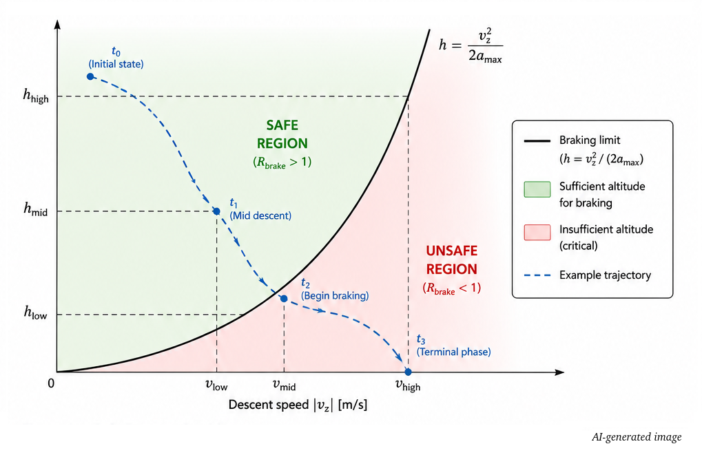
The black curve shows the minimum altitude required to decelerate to zero vertical velocity with maximum braking acceleration . State above the curve (green area) provide sufficient altitude margin , while states below the curve (red area) are dynamically infeasible and require immediate maxium braking.
The figure below illustrates how the controller switches between descent modes depending on the brake ratio during the landing trajectory.
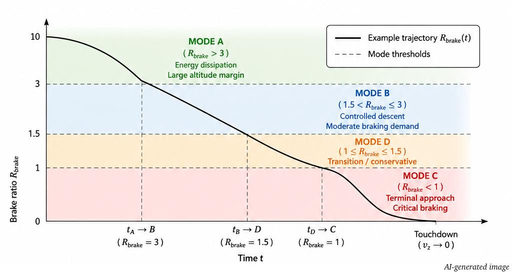
The brake ratio governs the controller's operating mode. As the spacecraft descends and decreasees, the controller transitions from energy dissipation (MODE A) to controlled descen (MODE B), then to a conservative transitions (MODE D), and finally to the terminal braking phase (MODE C) until touchdown.
Controller Characteristics
- Energy-based target descent velocity generation
- Brake-ratio-based descent mode selection
- Adaptive gain scheduling
- Gravity compensation
- Thrust saturation handling
- Compatible with normalized propulsion interfaces
The controller provides a structured guidance and control baseline for reproducible lunar landing simulations. It is not intended as a flight-certified landing controller, but as a transparent and extensible research model for autonomous descent experiments.