Quaternion Attitude Controller
1. Model Overview
The SDF attitude-control model provides two complementary rotational control modes for a spacecraft equipped with reaction-control-system thrusters:
- Kill Rotation damps the spacecraft body angular velocity toward zero without prescribing an absolute target attitude.
- Stabilize captures the spacecraft attitude at activation and subsequently drives the vehicle back toward this reference attitude while simultaneously damping angular motion.
The attitude-hold formulation operates directly in quaternion space. Euler-angle conversion is therefore not required inside the control model, avoiding the singularities associated with three-angle attitude parameterizations.
The controller output is interpreted as a three-axis rotational command. The physical torque acting on the spacecraft is generated by the separate RCS actuator and control-allocation models.
2. Quaternion Attitude Representation
Spacecraft orientation is represented by the normalized quaternion
with scalar component and vector component
Because the quaternions and describe the same physical orientation, the attitude-control formulation explicitly resolves this sign ambiguity when evaluating the rotational error.
3. Quaternion Attitude Error
In Stabilize mode, the current attitude at the activation instant is stored as the reference attitude:
The attitude error is then formed as
where denotes quaternion multiplication. For a unit quaternion,, so the inverse corresponds to the quaternion conjugate.
To enforce the shortest rotational representation, the sign of the error quaternion is selected such that
If , all quaternion coefficients are multiplied by . The proportional attitude error used by the controller is the vector part
4. Kill Rotation
Kill Rotation is a pure angular-rate damping mode. Its control objective is
where is the spacecraft angular velocity expressed in the spacecraft body-fixed frame. The three axes are treated independently according to
with component-wise multiplication. A small angular-rate deadband avoids unnecessary RCS commands once the remaining rotation becomes sufficiently small:
Unlike Stabilize mode, Kill Rotation does not contain an absolute attitude-restoration term. A stationary spacecraft therefore produces zero command even if its orientation differs from an earlier attitude.
5. Stabilize Control Law
Stabilize combines quaternion attitude-error feedback with direct angular-rate damping. The current control law is
The proportional term drives the spacecraft toward the captured reference orientation, while the derivative term removes rotational kinetic motion and provides damping around the target state.
The resulting equilibrium objective is therefore
6. Attitude Error Angle
For evaluation and switching logic, the quaternion error is converted into a single physically interpretable angular deviation. After shortest-path sign handling, the total attitude error angle is
The clamping operation protects the inverse cosine against small floating-point excursions outside the mathematically valid interval.
7. Hysteresis for Discrete RCS Actuation
The current RCS actuation model is binary. A non-zero rotational command can therefore result in full thruster activation even when the continuous-valued controller output is very small. Initial attitude-hold tests showed that a single deadband leads to repeated switching around the target state.
SDF therefore applies a two-threshold hysteresis to the Stabilize correction state.
Correction OFF condition
Correction ON condition
Between these inner and outer thresholds, the previous correction state is retained. The resulting Schmitt-trigger-like behavior reduces rapid RCS chatter while preserving a bounded attitude-hold region.
8. Model Variables and Parameters
| Symbol | Description | Unit | Frame / Domain |
|---|---|---|---|
| Captured target attitude quaternion | – | Attitude representation | |
| Current spacecraft attitude quaternion | – | Attitude representation | |
| Quaternion attitude error | – | Relative attitude | |
| Vector part of the quaternion attitude error | – | 3-axis control error | |
| Spacecraft body angular velocity | rad/s | SBF | |
| Attitude-error proportional gain vector | – | Controller parameter | |
| Angular-rate damping gain vector | – | Controller parameter | |
| Total quaternion attitude error angle | rad / deg | Scalar error metric | |
| Stabilize rotational control command | – | SBF control axes |
9. Assumptions and Simplifications
- The attitude quaternion is assumed to remain normalized within numerical tolerance.
- The target attitude remains fixed for the complete duration of one Stabilize activation.
- Angular velocity is directly available in the spacecraft body-fixed frame.
- Controller gains are currently constant and axis-wise.
- No integral control term is applied.
- The controller itself does not model actuator delay or thrust-transient dynamics.
- The hysteresis thresholds are currently engineering parameters rather than analytically optimized switching surfaces.
- RCS allocation remains binary in the present SDF Light formulation.
10. Verification Results
The following figures are generated from exported SDF telemetry and illustrate the measured closed-loop behavior of the current quaternion attitude controller.
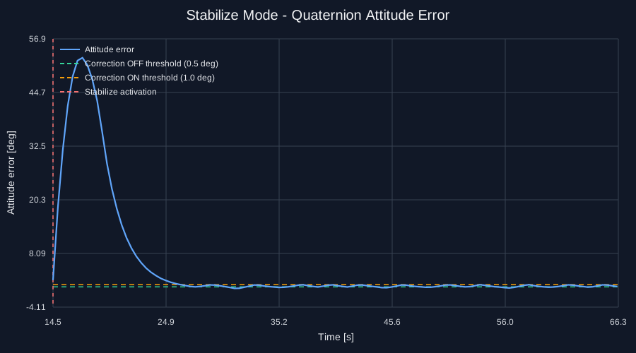
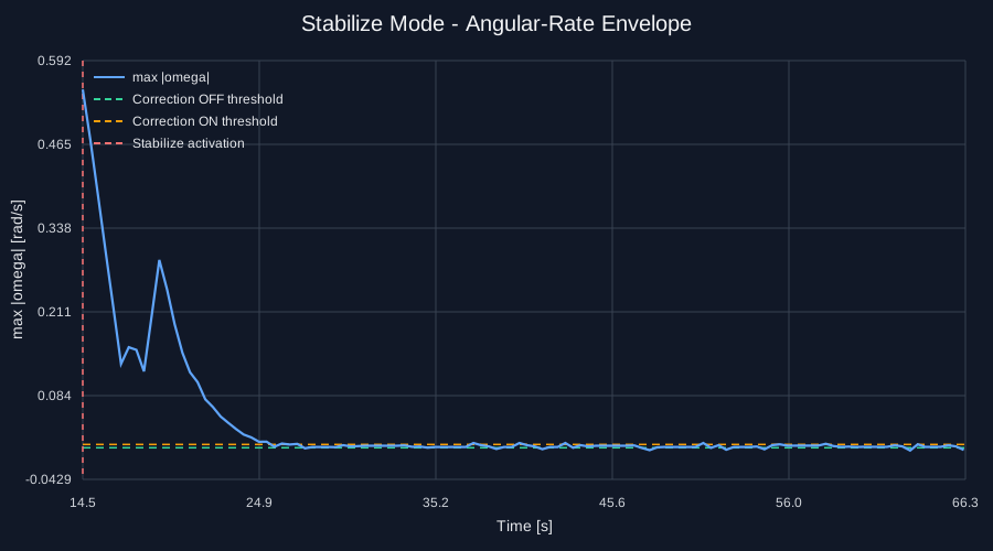
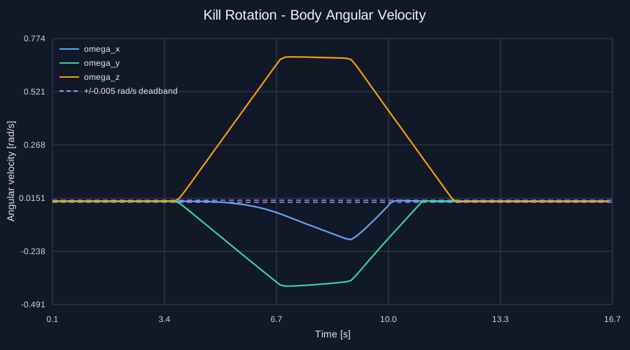
The telemetry also reveals the limitations of the present binary actuator interaction: after the main transient has decayed, short RCS correction bursts remain visible as the state moves between the hysteresis thresholds. This behavior is bounded and suitable for the SDF Light model, while providing a measurable basis for future work on pulse modulation, control allocation, and actuator-aware switching laws.
11. Validity and Limitations
The current formulation provides a compact quaternion-based attitude-control model that is suitable for closed-loop 6DoF simulation with discrete RCS actuation. It correctly distinguishes between pure angular-rate damping and absolute attitude hold, avoids Euler-angle singularities, and produces bounded attitude regulation in the tested multi-axis cases.
The controller should not yet be interpreted as an optimized spacecraft attitude-control law. In particular, the continuous PD output is coupled to a binary thruster system, while the hysteresis limits are fixed engineering values. Future extensions may therefore formulate the control problem directly in rotational phase space and include minimum-impulse-bit behavior, pulse modulation, actuator constraints, and improved control allocation.
12. References
- Wertz, J. R. (Ed.), Spacecraft Attitude Determination and Control, D. Reidel Publishing Company, 1978.
- Wie, B., Space Vehicle Dynamics and Control, 2nd ed., AIAA Education Series, 2008.
- Schaub, H. and Junkins, J. L., Analytical Mechanics of Space Systems, AIAA Education Series.