Spacecraft Configuration
The Spaceflight Dynamics Framework (SDF) is designed as a research-oriented simulation environment for spacecraft dynamics, descent guidance, control algorithms, propulsion system evaluation, and telemetry-driven analysis.
Before starting a simulation run, users select a spacecraft configuration from a set of JSON-defined vehicle profiles. Each configuration defines the physical, propulsion-related, and controller-relevant parameters used by the C++ simulation backend.
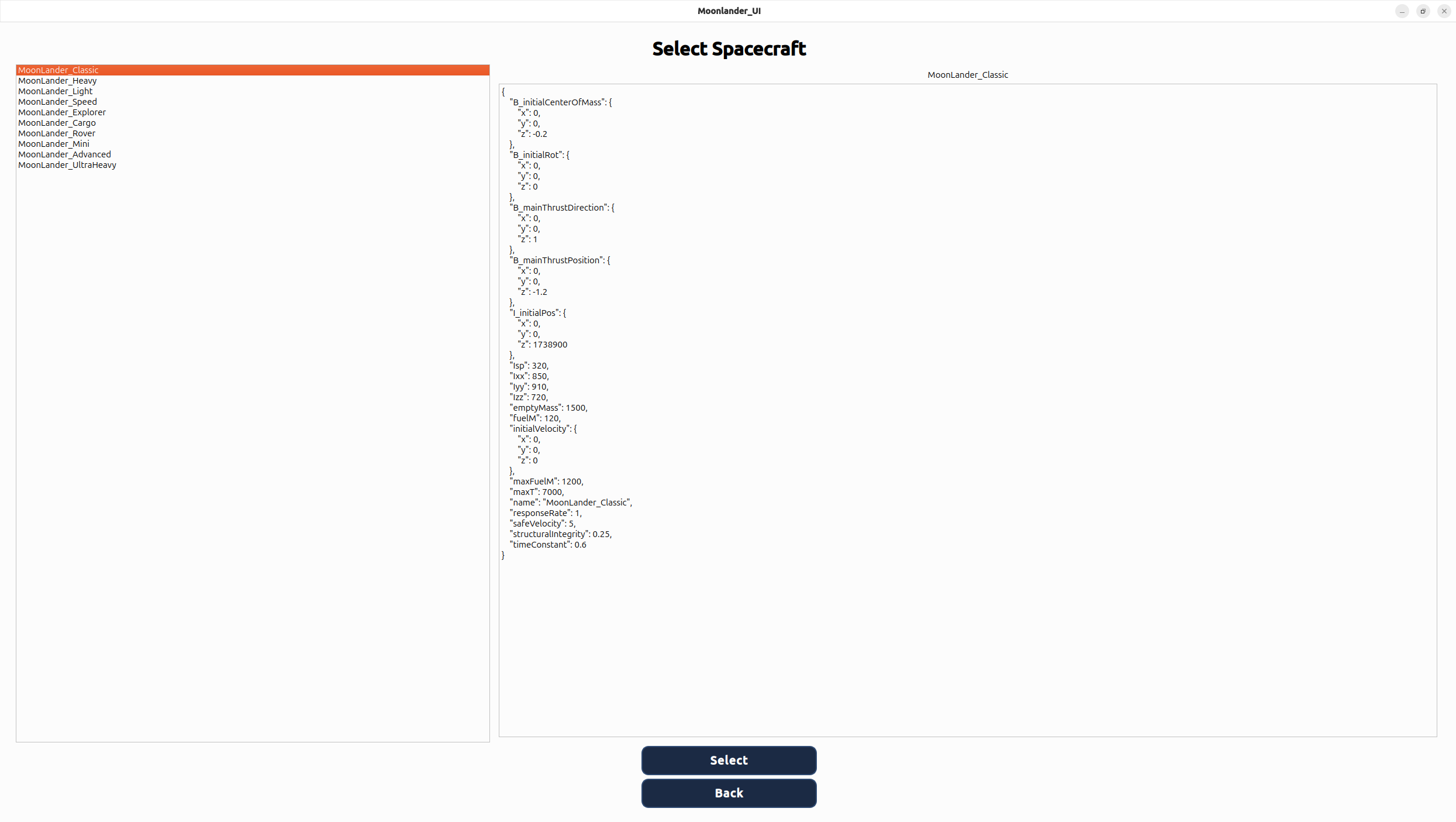
Figure 0 — Spacecraft Selection Interface. Spacecraft configurations are selected before entering the cockpit. Each vehicle profile is defined externally and contains mass properties, propulsion data, tank definitions, controller-relevant limits, and initial mission conditions.
The selection interface separates configuration management from the simulation engine. This allows new spacecraft variants, propulsion layouts, fuel tank architectures, and test scenarios to be introduced without modifying the core simulation code.
If no spacecraft is selected explicitly, the first configuration defined in the JSON file is used as the default. This guarantees that the backend always receives a valid and reproducible initialization state.
Simulation Demonstration
The following demonstration shows the cockpit interface during a representative descent run. The interface is intended not only as a visual cockpit, but also as an engineering and analysis tool for evaluating landing controllers, propulsion behavior, command response, and vehicle state evolution.
All displayed quantities are computed by the underlying C++ physics model and updated in real time through the frontend telemetry path.
Figure 1 — 1500 m Descent Demonstration. Representative descent from 1500 meters using an adaptive descent controller. The cockpit displays navigation state, fuel consumption, propulsion activity, controller output, and spacecraft status in real time.
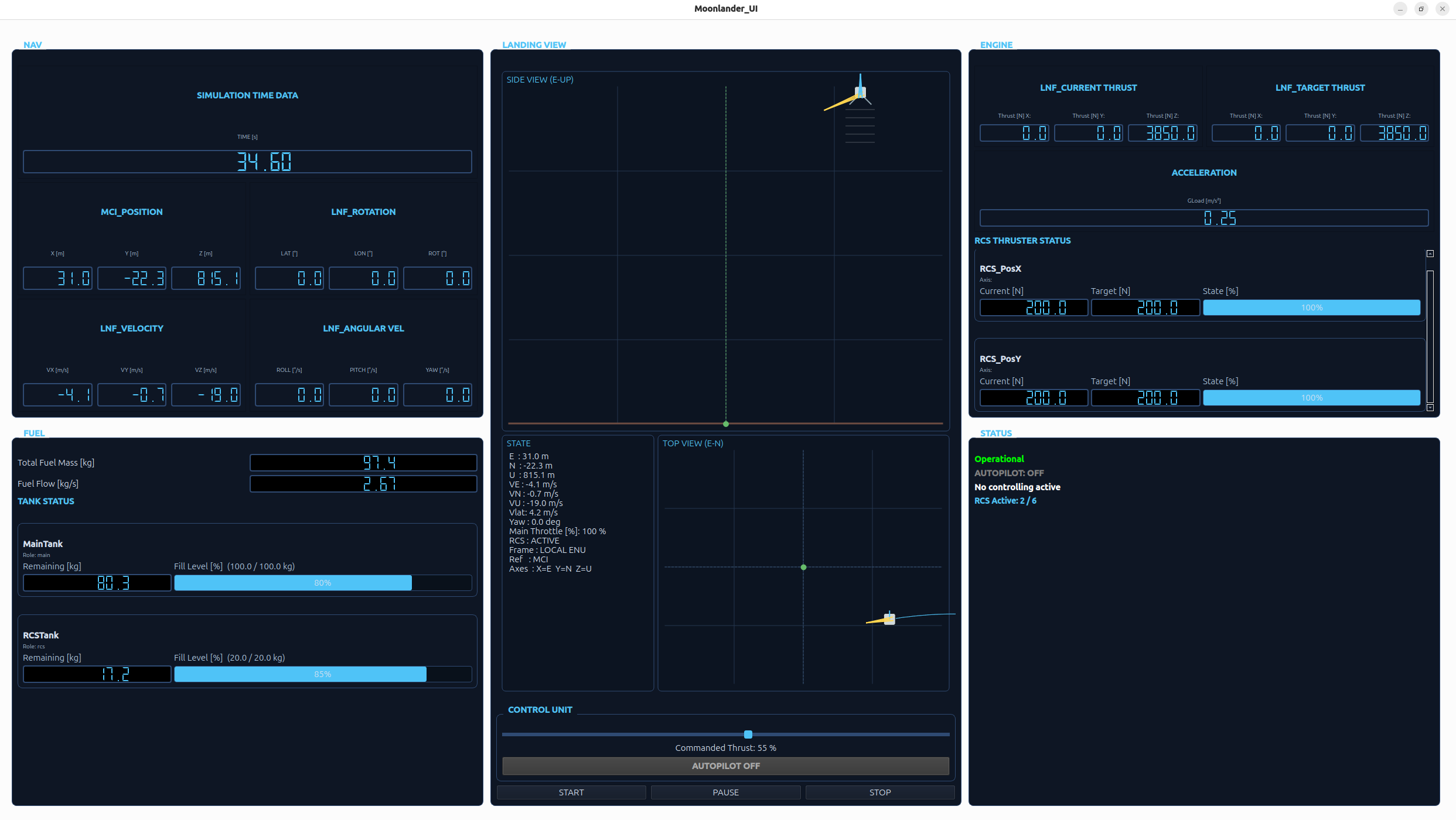
Figure 2 — RCS Telemetry Integration in the Cockpit Interface. The cockpit visualizes Reaction Control System activity at multiple abstraction levels: the Landing View indicates whether RCS activity is present in the vehicle state display, the STATUS block reports how many configured RCS thrusters are currently active, and the ENGINE block exposes thruster-level thrust information when individual RCS engines are firing.
Research-Oriented Cockpit Interface
The cockpit interface has been restructured to support a more scientific workflow. Instead of only presenting a simplified landing animation, the interface exposes vehicle state, propulsion state, control activity, and controller-relevant telemetry in a way that supports debugging, controller comparison, and future data export.
NAV — Navigation State
The navigation section displays the spacecraft's current kinematic state in the local navigation frame. The interface is prepared around the ENU convention: East, North, and Up. This makes the displayed state directly usable for landing analysis, lateral drift evaluation, and controller debugging.
FUEL — Propellant and Tank State
The fuel section has been extended from a single global fuel display to a dynamic tank-based representation. Each configured fuel tank can be displayed individually with its name, role, remaining propellant mass, and fill ratio. A visual fill bar shows the remaining propellant relative to the tank capacity.
This supports spacecraft configurations with multiple tanks, such as separate main engine and RCS propellant reservoirs, and makes fuel usage easier to analyze during controller tests.
LANDING VIEW — 2.5D Situational Visualization
The landing visualization has been upgraded from a simple one-dimensional altitude display to a lightweight 2.5D situational view. It shows the spacecraft in a local ENU frame using a side view for vertical motion and a top view for horizontal drift and target-relative motion.
The view includes trajectory history, velocity vectors, target reference, yaw indication, and a compact state overlay. The state overlay also indicates RCS activity, allowing the user to immediately see whether translational control thrusters are contributing to the current vehicle motion.
ENGINE — Propulsion, RCS Activity and Loads
The propulsion section displays thrust-related telemetry for the main engine and the Reaction Control System. Main engine thrust is shown as aggregated force output, while RCS activity is displayed dynamically only when individual thrusters are active.
For active RCS thrusters, the cockpit shows the corresponding thruster name, axis assignment, current thrust, target thrust, and actuator state. This keeps the cockpit compact during inactive phases while still exposing detailed propulsion behavior during manual or automated translational control.
CONTROL — Autopilot and Controller Output
The cockpit reports whether the autopilot is active and displays controller output such as active mode information. This is especially relevant for testing different descent controllers and comparing their behavior under identical simulation conditions.
STATUS — Spacecraft State Machine and RCS Activity
The status section reports discrete spacecraft states such as OPERATIONAL, LANDED, CRASHED, or DESTROYED. These states provide a clear interpretation of the simulation outcome and can be used later for automated evaluation of landing performance.
In addition, the status block reports the number of active RCS thrusters relative to the number of configured RCS engines, for example RCS Active: 3 / 6. This gives an immediate overview of current translational control activity without requiring the user to inspect every individual thruster.
Scientific Use Case
SDF is intended to support the development and evaluation of spacecraft guidance and control strategies. The cockpit interface therefore focuses on telemetry visibility, reproducibility, observability, and system behavior analysis rather than visual realism alone.
Planned extensions include structured simulation data export, controller comparison workflows, and plotting tools for post-run analysis. Relevant quantities include altitude, vertical velocity, lateral drift, fuel consumption, thrust commands, tank usage, RCS activity, controller state, and final touchdown conditions.
The current demonstration remains a lunar descent scenario, but it now acts as a validation use case for the broader Spaceflight Dynamics Framework rather than defining the limits of the project.